BEGINNING
Apple designed the Apple 12" RGB Display for use with the Mac LC series (which also includes the LCII, LCIII, LC475) or the Mac IIsi. Each of these computers have the same case front curve style, so if you place the RGB display onto the computer it almost looks like a it is attached to the computer case. However, the frustrating limitation of this display is that the computer can only use a 9" desktop: the display resolution is fixed at only 512 x 384 pixels, even though the LC series computers are capable of driving higher resolution displays such as VGA monitors (a video RAM expansion is necessary if you want to see more than 16 colors at higher resolutions). Lots of software already exists which requires at least 640 x 480 display resolution, and some programs even need 1024 x 768 pixels.
One day I bought the magazine, MAC POWER (June 1998) and found the article I was hoping for, entitled:
"Tak's Kaizou-dou 7 'Modify Apple 12" RGB Display to high resolution mode' "
I read it several times to thoroughly understand the modification and adjustments involved. Next I looked at Tak's MYSTIC ROOM, where I found some corrections to that article (regarding capacitors). It took another six months, however, until I actually attempted to modify my display!
CONTENT
For details, please check Mr. Tak's book. Here I'll only briefly outline the steps involved.
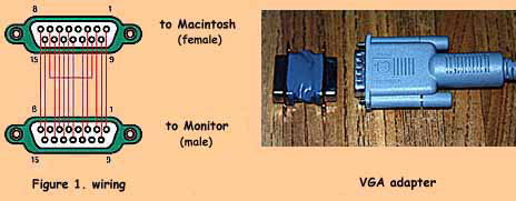
- making a VGA adapter
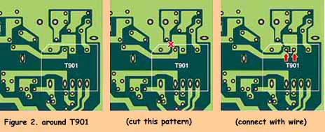
- changing the tap of flyback transformer T901
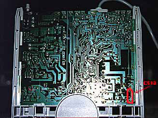
- decreasing the capacitance of high voltage capacitor C513
- adjustments
1. Making a VGA adapter: Macintosh computers recognize monitors according to differences in connector wiring. A special adapter is needed to "fool" the Macintosh into thinking that the RBG display is a VGA monitor. Get a male and a female 15 pin D-subminiature connector, and wire them as shown in Figure 1 below:
2. Changing the flyback transformer tap: To keep proper screen brightness and horizontal width you need to change the tap of flyback transformer T901, which increases the horizontal deflection voltage. To do this you need to cut the printed circuit pattern at the point indicated below and add a jumper beside it. Figure 2, below, shows where to cut the printed circuit and add the jumper:
3. Decreasing the capacitance of high voltage capacitor C513: To prevent both sides of the display from being cut off, you need to decrease the horizontal deflection voltage, controlled by capacitor C513 (please see the photo below), which is a ceramic capacitor (rated voltage >1.6kV, original capacity 6200pF). You probably need to reduce the capacitance, for example, to around 5600pF still rated for >1.6kV. However, the actual capacitance that will work best varies between individual monitors, so you should get 4 ceramic capacitors (rated voltage >1.6kV; 5600pF, 4700pF, and 2 x 330pF) and then you can select the capacitance that works best by trial and error. Remember that the total capacitance simply adds up when you install capacitors in parallel. Try 5600 pF, 5360 pF (4700+2x330), 5030 pF (4700+330), and 4700 pF. Another possible combination is 6220pF (5600+2x330), but you probably won't need to use that combination because it is similar to the original, although I found it useful during troubleshooting (see later).
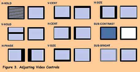
4. Adjustments: This is the most importantstep. The VGA adapter and modified flyback transformer tap alters the video state, so you must readjust the monitor. In particular, you must adjust H-HOLD, H-PHASE and SUB-CONTRAST. Please read the record of my actual experience and thoughts about this in the next section.
You should be able to find the locations of the video adjustment controls by searching for their names imprinted on the circuit board. All are potentiometers (variable resistors) except for the H-SIZE control (sets the horizontal display width), which is a coil situated on the right side of the picture tube. Please see Figure 3, below, which depicts the effect of each adjustment control:
SHOPPING
I went to Akihabara to buy parts to for this modification.
15-pin D-sub connectors: Available at many outlets, but price varies by material and quality. A grounded metal cover shell may be stronger and more reliable than a plastic shell. Shop around for the best combination of price and quality.
Ceramic capacitors: Not many shops sell capacitors rated for 1.6kV or more. I bought them at CR (the Japan Railways' trams run over the shop).
Tools: I bought a set of coil core drivers at a tool shop. You should buy a set because adjusting the H-SIZE coils needs a specially shaped driver. The driver must be made from a non-conductive, non-magnetic, soft material, usually plastic. If it is conductive, you could get a shock from the high voltages near the coil. If it is magnetic or ferrous then it will affect the magnetic field inside the coil, making it very difficult to adjust the coil properly. If it isn't a soft material then you might fracture (break) the coil core, which is made of relatively soft ferrite. For safety, it's also a good idea to use a plastic slot-shaped driver to adjust the variable resistor video controls. Always be gentle when adjusting the coil core or video controls.
MODIFICATION (the first day)
Initially I made a VGA adapterfrom two back-to-back D-sub connectors. I used resistors to connect the straight through pin-to-pin connections because I thought it would be easier. I used insulated hook-up wire to connect the monitor sense pins. Then I wrapped the assembly with plastic electrical tape, as was shown above in Figure 1.
But when I used my VGA adapter I found that it kept bending in the middle. It probably would have been better to connect directly for straight connections and to cut the contacts off where there were to be no connections, making a rigid adapter assembly.
Next I opened up the monitor case. Removing the back cover of the monitor case involves more than just taking out the 2 screws: there are also 2 clips on the top side of the cover. They are about 4 cm in from sides and you have to push hard to release them.
After removing the cover I changed the tap of flyback transformer T901, using thick wire to jumper the new connection, as was shown above in Figure 2.
Then I changed capacitor C513. I gently sucked the solder off with a copper desoldering braid and removed the capacitor (if you are too rough with this step you might tear the printed circuit contact off the board). I installed a 5600 pF capacitor initially.
After a coffee break I connected it to LC and switched on the power! ....But I couldn't see anything on the screen. I could hear a crackle when I turned it on but the screen remained black. I tried adjusting all of the video controls but the result was the same.
I broke into a cold sweat. I thought I ruined the monitor and put the cover back on. As I went to bed I wondered how much a second-hand monitor would cost in Akihabara!
MODIFICATION (the second day)
The next day I went to work. At lunch time I visited MYSTIC ROOM, where I discovered a bulletin board. I searched for similar cases in the archives there and found exchanges between Tak and others who had the same problem as myself. After read that information, I understood that actually my monitor wasn't ruined! (yet)
According to the bulletin board archives, my monitor was in the state that activated an overload limiter. I had to correct this problem before going any further.
After my children went to bed I returned to work on my monitor. To check if the monitor was ruined, I undid all of my modifications by removing the VGA adaptor, and putting back the original flyback transformer tap. Rather than risking damage to its circuit board contacts, to restore capacitor C513 to a capacitance close to the original I added 2 x 330 pF in parallel with my 5600 pF capacitor. I connected the display directly to the Mac LC and switched on the power. To my very great relief, the monitor displayed something, although it needed video adjustment. I felt a lot better, however.
Next I switched it off, reconnected the cable through the VGA adapter, and switched it on again. It displayed something and still needed video adjustment. I adjusted H-HOLD and tried to improve the video. Sometimes the screen turned black because I turned this control too far in the wrong direction, causing the overload limiter to activate. When this happens, just turn it off, turn down the SUB-CONTRAST, and try again. It may not always be the case for different monitors, but I found that the stable point for H-HOLD was just slightly clockwise from the center position, so it's easy to find it by slowly turning the control clockwise. If you turn it counter-clockwise then the overload limiter will activate.
I adjusted the video as good as possible, then turned it off and let it sit for about 30 minutes. It takes a while for the high voltage charge in the capacitor to discharge, so you should wait to be safe. Then I changed the tap of the flyback transformer. After this the monitor displayed the VGA image much quite well. I adjusted H-HOLD a little then H-PHASE and H-SIZE. I could get a good the horizontal width but couldn't see the left edge of the desktop, a sign that I needed to try different capacitor values.
I was anxious to continue working, but forced myself to leave it switched off for another 30 minutes. This time I removed one of the 330 pF capacitors that I had wired in parallel with C513 (5600 + 330 = 5930 pF), but I still couldn't see the left edge. I left it off for another 30 minutes and then removed the other 330 pF capacitor (C513 = 5600 pF). Then I could see almost the entire desktop. I adjusted the horizontal and vertical size and centering controls and then the display was almost perfect. I went to bed very late, but happy that I had succeeded in modifying my display for VGA operation.
MODIFICATION (the third day)
Because the left edge was still slightly cut off, I further reduced C513 to 4700 + 2 x 330 = 5360 pF, but then it was still slightly cut off. After waiting another 30 minutes with the power off I took off 330 pF so C513 was 4700 + 330 = 5030 pF. At last the monitor displayed the whole desktop perfectly. Note that it's easier to adjust H-PHASE if you first over-brighten the black frame around the desktop using the BRIGHT control.
Then I didn't have to modify the hardware any further, so I did the final adjustments. If you will increase the vertical display size as much as possible then the display will be distorted. Adjust the horizontal size to balance the vertical size so that characters are displayed in their proper proportions on screen, while filling the display area as completely as you like. I found it easy to adjust this balance by displaying a checkerboard pattern on the desktop (use an old version of the Monitors control panel that has a Convergence function if you have it, such as version 3.3.1 which came with MacOS 6.0.1, or create a suitable pattern in a drawing or painting program).
THOUGHTS AFTER MODIFICATION
- Working process
- If you modify without understanding then you won't be able to adjust the display very effectively. So I suggest you to do the process at MODIFICATION (the second day) later to your preference. There can be differences between individual monitors. There is always the possibility that you might ruin your monitor with this modification, so attempt it at your own risk.
- Be careful with high voltages!
- The display picture tube is a large vacuum tube. There are high voltage circuits inside the monitor, unlike other electric devices, especially in and around the picture tube and flyback transformer. Always be very careful during modification and adjustment. You could be injured or even killed by an electric shock.