| English | -> Computer | -> MODIFICATION | -> Apple 12" mod for VGA (2) | -2000.07.12 Updated- |
[ Apple 12" RGB Display Modified for VGA mode (2) ]
As I said before, my VGA adapter was not very strong, and my children broke it by rough treatment. So I decided to modify monitor sense of the original cable connecter itself so that it would be permanently wired for VGA mode.
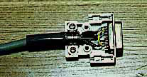
My plan was to remove the old connector cover, change the wiring, then put a new cover on. But I found that the wiring inside was embedded in white plastic so I couldn't easily change it! So instead I cut off the original connector at attached the cable directly to a new D-sub connecter. I tested the connection between the cable and pins with a continuity tester, but there were no connections for horizontal or vertical sync signals. I guessed that this wasn't a problem since a mixed sync signal was connected, but I wanted to be sure that there wasn't some special device or connection embedded in the white plastic. So I began to shave it with a razor. One hour later I found that there weren't any embedded connections. So the connection for VGA mode was as follows:
| Pin | Signal | Cable |
|---|---|---|
| 1 | red video output GND | shield braid of white wire |
| 2 | red video output | core of white wire |
| 3 | mixed sync signal | clear twisted wire |
| 4 | monitor sense line 0 | (no connection for VGA mode) |
| 5 | green video output | core of black wire |
| 6 | green video output GND | shield braid of black wire |
| 7 | monitor sense line 1 | connect to pin 10 for VGA mode |
| 8 | unused | no connection |
| 9 | blue video output | core of red wire |
| 10 | monitor sense line 2 | connect to pin 7 for VGA mode |
| 11 | sync signal GND | blue twisted wire |
| 12 | vertical sync signal | no connection |
| 13 | blue video output GND | shield braid of red wire |
| 14 | sync signal GND | no connection |
| 15 | horizontal sync signal | no connection |
You should prepare the ends of the shield braids carefully, twisting them tightly and tinning them with solder and none of the metal strands stick out, otherwise they may touch other wires or pins and cause a signal short-circuit. The original white plastic embedding was probably done to prevent these shield braids from causing short-circuits, so if you like you can embed your new connections in a non-conductive plastic epoxy. Another thing you can try is to insulate each prepared shield using plastic spaghetti or heat-shrink tubing. My new the connecter continues to work very well, thank you very much! Note, as shown in the picture below, that it is a good idea to use a grounded metal shell instead of a plastic one, to shield the wires and make the connection stronger.
